
Spring is here and Summer is fast approaching! As we approach the warmer months of the year, HVAC technicians of all kinds start to see more AC system breakdowns. Your air conditioning system was most likely hibernating through the cool winter months, so of course when it's needed the most, it breaks down at the worst possible time . This is a common story heard from owners of commercial and residential air conditioning units alike.
While having air conditioning in your private residence is essential, keeping commercial air conditioning systems operating 24/7 is critical for operations. System downtime can cost companies thousands of dollars by driving away customers, damaging temperature sensitive products, and tarnishing a company’s reputation. One very serious malfunction that can create hours of air conditioning down time, is compressor failure.
The compressor is known as the “heart” of an air conditioning system. It pumps refrigerant throughout the HVAC system, which drives the process of conditioned air. If a compressor is defective and out of service, your HVAC system will only blow warm air. In commercial HVAC applications, diagnosing AC compressors can be complex for inexperienced technicians. A type of compressor in particular that causes many questions is a 3 phase AC compressor.
In this article, we will go over the proper procedures to diagnose a faulty 3 phase AC compressor. Be aware that 3 phase electric is used mainly in commercial applications and is typically 460 Volts! It is extremely dangerous to work with and can cause serious injury or even death. If you are an untrained and/or unlicensed individual, please do not try anything mentioned in this article. Ask your local HVAC professional for help.
Diagnosing a faulty HVAC system
A very important initial step to diagnosing an HVAC system is talking to the customer. Customers can save you a lot of time in diagnosis, by narrowing down what could be wrong with the system. Important questions related to a faulty compressor would be: were there any tripped electrical breakers? Have there been any loud noises coming from the HVAC system? Has the system been cooling mildly or not at all? How long has the system been down? Is this the first time this has happened and what are the previous issues with this system?
The more information you gain about the system, the faster you can get that cold air blowing again!
Identify the type of compressor
Typically, in residential electrical applications, you will see what’s called dual phase, split phase, or single phase electric. If you observe the electrical disconnect box or the electrical panel of the HVAC unit, you will find two power legs and a ground leg, supplying power. If you test the voltage between Line 1 and Line 2 with a voltmeter it will read approximately 220 volts. In a 3 phase electrical application, if you observe the electrical disconnect box or the electrical panel of the HVAC unit, you will find three power legs and one ground leg feeding the HVAC unit. If you test the voltage between Line 1 and Line 2 with a voltmeter it will read approximately 460 volts.
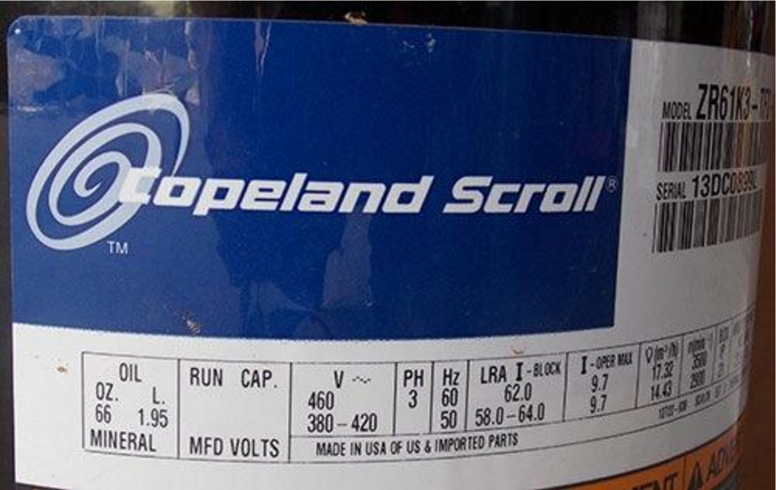
An easy way to identify if an AC compressor is 3 phase, is to read the manufacturer’s tag located on the compressor. View the example picture of the Copeland Scroll compressor manufacturer tag for reference. In the picture, observe the lettering “PH”, you will see a 3 listed below it. That number 3 indicates it is a 3 phase compressor. If you also look at the section that has a “V” at the top, it lists the number “460” below it. This indicates that the compressor is for 460 Volt applications. Typically 3 phase electrical systems are approximately 460 volts. If this compressor was a single phase compressor, it would read as follows. Under the “PH” section it would list the number “1”, for single phase. Under the “V” section it would list “220” or “208”, for 220 Volt applications. If the compressor tag is faded or unreadable, this information can be found on the manufacturers tag located on the exterior of the HVAC system (where the model and serial number or located). If you still cannot find the information you need from the manufacturer tags, then call the manufacturer and ask for this information. Information such as refrigerant type, age of the system, proper running amperage, proper voltage, the model number and the serial number can be found on the exterior of the HVAC system, on this tag. All of this information is vital when diagnosing an HVAC system.
Take a look at the electrical disconnect box
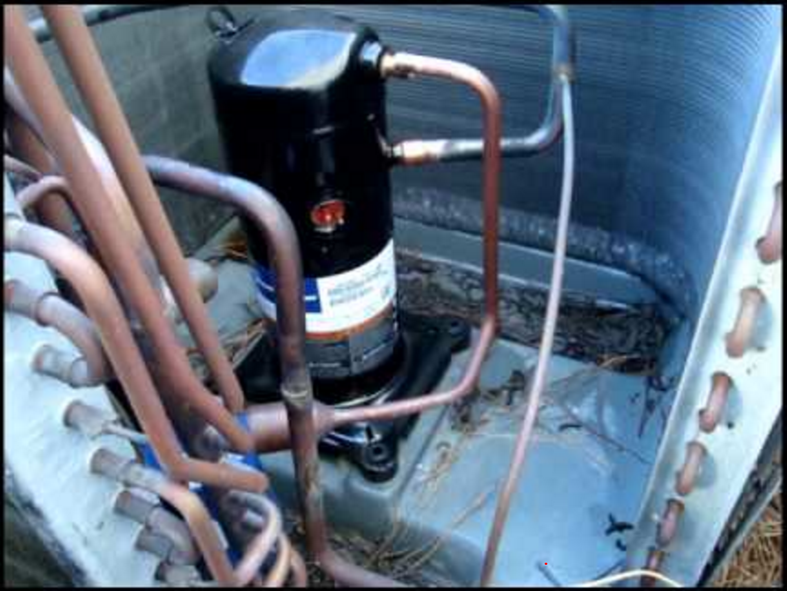
The next step, is to locate the thermostat and manually turn it to cool, while turning the set temperature at least 10 degrees lower than the room temperature. If the HVAC system is located on the roof, you will want to minimize the amount of times you go up and down the service ladder. After locating the HVAC system, first shut off the power at the electrical disconnect box, for safety. Remove the panels containing the electrical components and the AC compressor. View inside the electrical panel for burnt wires, loose wire connections, or anything that catches your eye as out of place. Smell for burnt wires or insulation.
A common issue for compressor failure is loose or faulty wiring, especially at the electrical disconnect box. Check the electrical terminals attached to the compressor for burnt or shorted wires.
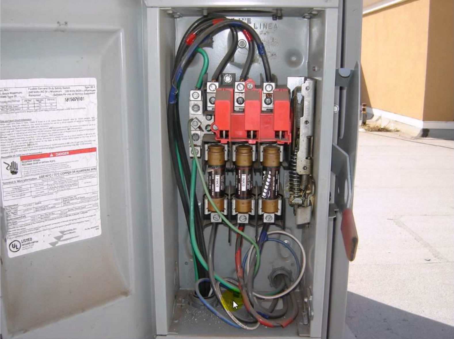
Now you can turn the power back on at the electrical disconnect box. See the picture to the right as an example of a 3 phase electrical disconnect box. Using a Voltmeter on the Load Side (bottom) test each voltage leg against the other. For Example, testing Line 1 (yellow) against Line 2 (red) displays the voltage of 474. Doing the same with Line 1 and Line 3, results in 473 Volts. Then Testing Line 2 and Line 3, results in 475 Volts. These measurements indicate that all voltages are almost equal to each other, which is what we want. If one of the Lines shows a significant difference in voltage, then there may be an issue with damaged wiring, loose wiring connection, a bad fuse, or faulty breakers. A common issue called “single phasing” is when one of the power legs reads “0” and causes malfunction to the system.
Test the contactor
Next, we must locate the contactor, verify that proper voltage is being received by the contactor on each power leg, and check the voltage leaving the contactor, for proper voltage. If the contactor is receiving 474 Volts on one leg, but has 236 Volts following the contactor on that same leg, then it is not sending the proper voltage through and may be defective. If the contactor coil is not pulled in, verify that it is receiving 24 Volts from the control wiring. If the contactor is not receiving 24 volts then follow these steps. Verify that the thermostat is sending 24 Volts to the contactor. Check if a low pressure or high pressure limit switch is preventing the contactor coil from activating. Check to see if the compressor’s thermal overload is activated, preventing the contactor coil from activating. A common issue associated with the contractor is when the copper pads get pitted and lose there ability to stay closed. This condition may cause voltage drop across the contactor.
Check refrigerant pressures
After checking the contactor for proper operation, it’s time to check the refrigerant pressures. Attach refrigerant gauges to the high and low side ports of the system. After turning on the system, let the pressures equalize for at least five to ten minutes, while monitoring the pressures. If the pressures are stagnant and do not fluctuate whatsoever, then most likely the compressor is not operating. Take an amp draw with an Amp meter of each electrical line feeding the compressor. If the compressor is receiving the proper line voltage to each leg and is pulling “0” amps then it is failing to start. If the refrigerant pressures are stagnant and the compressor is pulling extremely high amps that continue to rise, then it is most likely “in locked rotor amps”.
Troubleshoot compressor issues
A compressor showing locked rotor amps may show some of the following symptoms. The compressor may make a humming sound, that may increase in sound level over time. If the compressor continues to pull high amperage it may eventually cause the electrical breaker to trip. As the compressor pulls excessive amperage, while stuck in locked rotor amps, it is not able to be cooled by the refrigerant. The compressor will then continue to heat up and get very hot, which may trip the thermal overload switch. This is a protective feature in the compressor, that will shut off the compressor and try to prevent overheating. Do not ever touch a compressor to feel if it is hot! It can reach scalding temperatures before the thermal overload switch cuts it off. Use a thermal temperature gun to check the temperature of the compressor housing. A compressor in thermal overload may reach temperatures above 225 degrees Fahrenheit. A compressor that is pulling “0” Amps, that has proper line voltage, and has temperatures exceeding 225 degrees Fahrenheit is most likely in thermal overload. If a compressor is in thermal overload, wait at least 24 hours before diagnosing the system further, to give the compressor ample time to cool down.
What caused the thermal overload should be your next question. A compressor is essentially an electric motor. A motor has copper winding that can get shorts, become grounded, or have an open winding. These malfunctions can cause thermal overload or compressor failure. To check for any of these issues you first need to shut off the power at the electrical disconnect box. We recommend any time you will be removing wires to take a picture of the way it was originally wired for reference. You may also view electrical schematics on the inside of panels or manufacturer specifications for further reference.
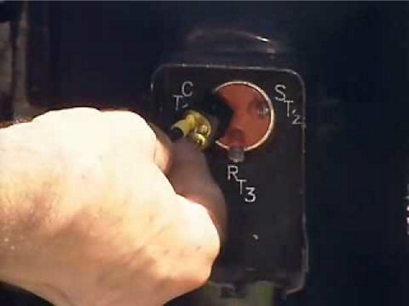
The compressor should have 3 electrical terminals attached to the housing from inside the compressor. On a 3 phase compressor, you will see the terminals listed as T1, T2, and T3. This is different from a single phase compressor which will have 3 terminals listed as S, R, and C (Start, Run and Common). See the picture for reference.
If the 3 phase compressor is a “scroll compressor,” be careful recording which wire is attached to which terminal. If you change the location of the wire, you may reverse it’s polarity. Reversing polarity will change the direction of rotation of the compressor. Sometimes improper wiring can cause a compressor to rotate in the wrong direction and cause it to “lock up” and fail. Three phase scroll compressors only rotate in one direction. It is simple enough on a 3 phase scroll compressor to swap the location of T1 and T2 to reverse the rotation and check if it was wired to rotate in the wrong direction. In 3 phase reciprocating compressors, they can rotate in either direction with out any issues. Although, if the reciprocating compressor has rotated in one direction for many years then it is unhealthy for the compressor to change directions, as it will cause more wear and tare to the compressor. Be advised that you cannot swap wires and terminals for single phase compressors.
3 Phase Compressor Internal Troubleshooting:
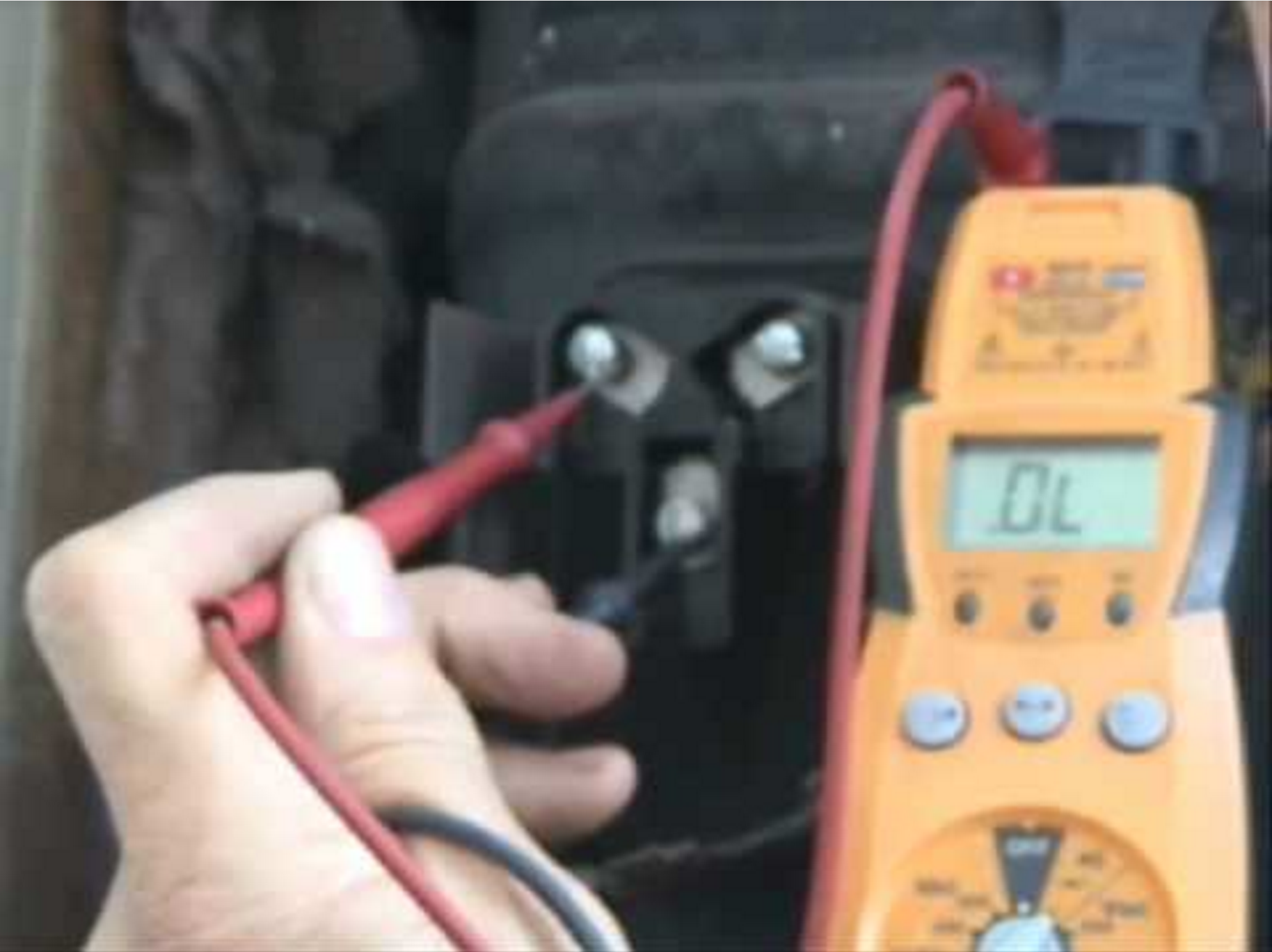
Checking a Short to Ground- Turn the Power off. Remove all of the wires off the terminals. Take an Ohmmeter and attach one probe to T1 then take the other probe and touch it to the metal housing of the HVAC system, the housing of the compressor, or the copper pipe. You may have to scratch or lightly sand the surfaces to remove dirt and have a clean finish. Make Sure the Ohmmeter is in the 1000 scale. You should get no resistance, or a reading of 0.L. If you get any reading of resistance then there is a short to ground in the compressor winding. Continue to test T2 and T3 in the same fashion as T1. A compressor must be replaced with a short to ground.
Checking for an Open Winding- To check for open winding in the compressor, you will use the Ohmmeter and attach 1 probe to T1 and the other probe to T2. If the Ohmmeter reads 0.L or infinity then there is an open winding. If the compressor is in thermal overload this may cause there to be an open winding between terminals and hence read 0.L or infinity. Wait for the compressor to cool down properly before testing again. Test between all terminals. If an open winding is found after the compressor is out of thermal overload, then it needs replacement.
Checking for Internal Short- Repeat the steps of checking for an open winding. In a 3 phase compressor, each Ohm reading from terminal to terminal should essentially be the same. For example, if you had an Ohm reading of 2 between T1 and T3, then you should have an Ohm reading of 2 between T2 and T3. So, you should get the same Ohm reading, approximately, across all terminals. If there is a significant difference in the readings then there may be a short in the compressor windings. (Note: In a single phase compressor with S, R, and C terminals the resistance readings will be different from each other. For Example S = 6 Ohms, R = 4 Ohms, and C = 2 Ohms is completely normal.)
Checking MegaOhms- A Megohmmeter is a tool used to measure resistance at a higher scale and can be a very useful tool when dealing with compressors. If a compressor has been malfunctioning or causing internal thermal overload, it can damage the insulation surrounding the windings. The integrity of the insulation can be deteriorated or oil could reach the windings, causing contamination. To check the integrity of the compressor’s windings, complete these steps. Using a Megohmmeter complete the same steps as “checking a short to ground” . The Megohmmeter can help determine if the windings are starting to fail to ground. A reading of 20 Megaohms or lower is an indication of a bad motor winding, which is failing to ground. A reading of 20 - 100 Megaohms is an indication of caution or degrading motor winding. A reading of 100 Megaohms and higher indicates good motor winding condition. The is device is extremely helpful as it can help determine motor breakdown and can be the determining factor in whether to keep or replace a compressor. We highly recommend HVAC technicians invest in a Megohmmeter. Here’s why, say you have a 3 phase AC compressor that randomly hits internal thermal overload every month or so. While you are testing the system everything checks out fine. You complete a resistance test with the Megohmmeter and gain the reading of 25 Megaohms. You list on the invoice that the compressor windings are near failure to ground and recommend replacement. The customer decides not to change out the compressor, as it is still intermittently working. He then calls back one week later and says you were completely right. This situation could have gone completely different if you did not have the Megohmmeter, as everything else tested completely fine. You would have left the job, stating to the customer that you found no issues and everything seems fine. Then the system breaks down in 1 week!
3 Phase Compressor Refrigerant Troubleshooting:
When monitoring refrigerant pressures, it is important to first observe the type of refrigerant contained in the system. Use AC gauges only on one type of refrigerant to minimize contaminating HVAC systems you service. Have an AC gauge for each type of refrigerant you encounter.
After learning the refrigerant type, look for the refrigerant chart, normally located on the inside of the metal panels of the HVAC system. Some manufacturers list these charts online in pdf form, if you search for the product by model and serial number. See the picture example below for reference.
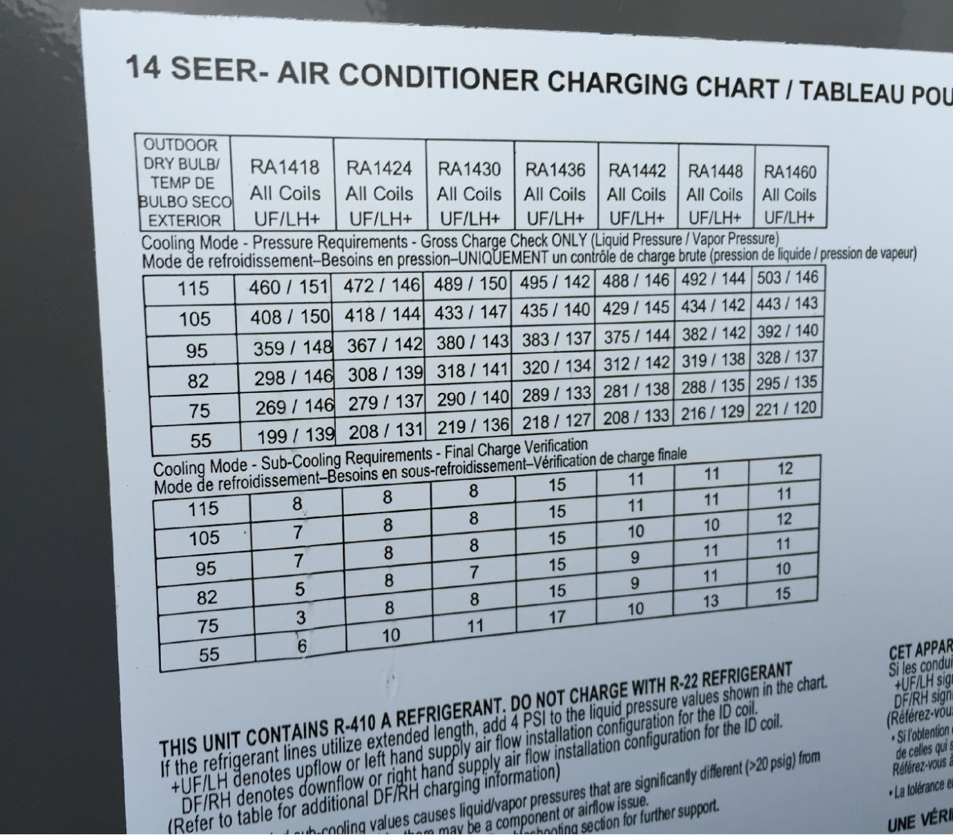
Let’s say, for example, we have a R-410a system and it is a 5 ton, 60,000 BTU system. So refer to the column in the picture labeled RA1460. To follow this chart, you must first measure outdoor dry bulb temperature with a thermometer. Let’s say it’s 82 degrees Fahrenheit outside. If you follow the chart across, you will see the pressures listed as 328/137. So that is indicating that the high side pressure should be approximately 328 psi and the low side pressure should be approximately 137 psi. The chart lists the proper sub cool related to outdoor temperature. So again, with a 82 degree outdoor temperature, sub cool should be approximately 11 degrees Fahrenheit. This particular system is equipped with a Thermal Expansion valve, so we test the sub cooling temperature when measuring for proper refrigerant charge. If the system was equipped with a piston or fixed metering device, then the chart would indicate the proper superheat per manufacturer guidelines.
Proper refrigerant charge is extremely important to the health of a 3 phase or any AC compressor. An undercharged system will cause the compressor to work under higher load and could potentially cause icing of the coil. An overcharged system can increase pressures dramatically, causing higher temperatures in the compressor and possibly internal thermal overload. HVAC systems may be equipped with high pressure limit switches, which shut down the system if refrigerant pressures get too high. A low pressure switch may also be equipped to shut down the system if pressures get too low. A helpful tool in higher end HVAC systems is a circuit boards that indicate fault codes, which list reasons for the system malfunction.
3 Phase Compressor Miscellaneous Troubleshooting:
Compressor Rotating in wrong direction- If you hear loud knocking from the compressor or humming then it may be locked up, with the power off, try reversing polarity by changing power legs on each terminal. The compressor should then reverse the direction of rotation. Again, scroll compressors are made to only rotate in one direction.
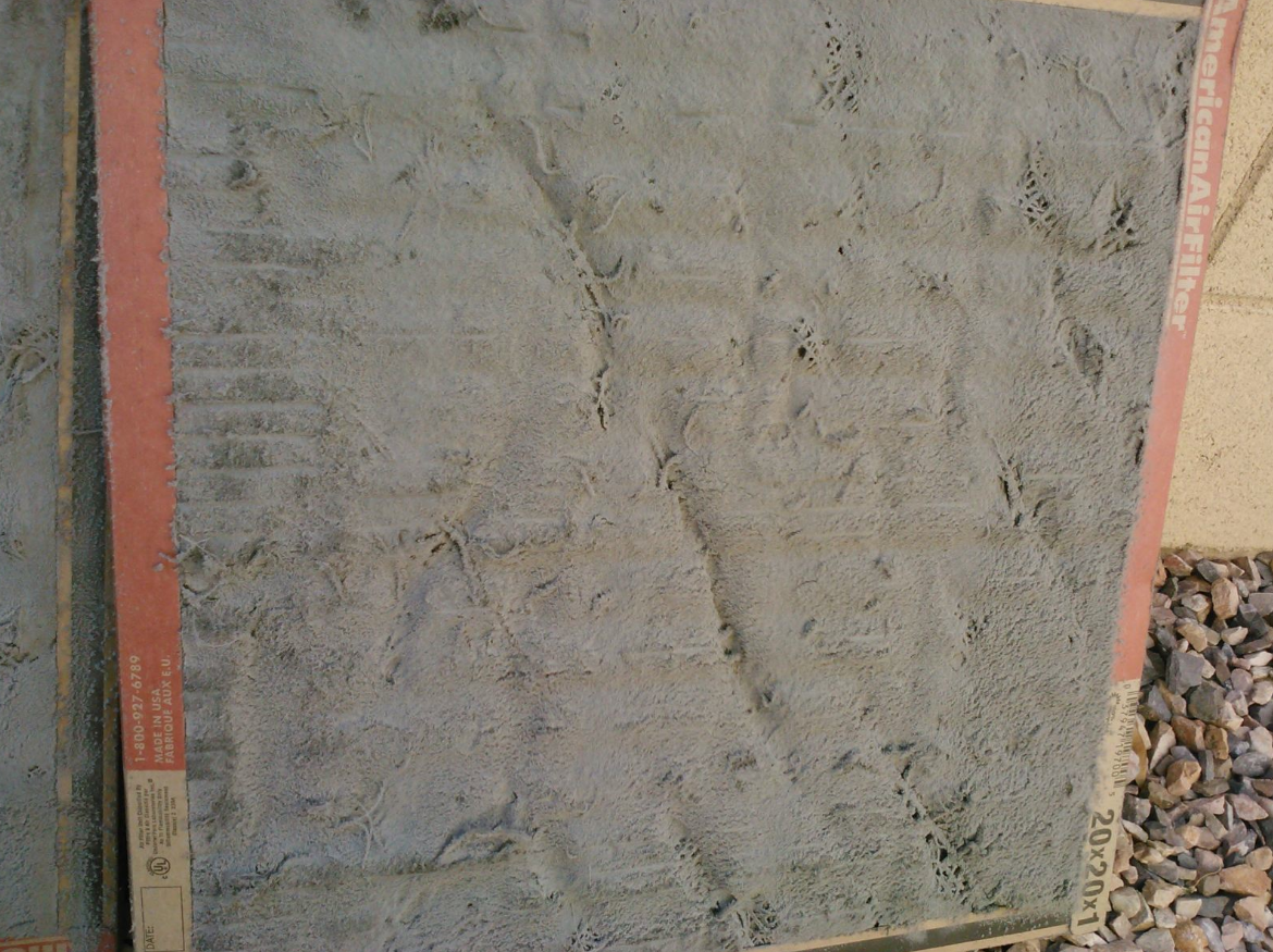
Dirty Filter or Dirty coils- Extremely dirty filters can cause increased static pressure and higher load to the system. The suction pressure will read lower than normal in this case. Remove and replace with a new clean filter immediately. Dirty coils may cause the same issue and need to be cleaned or replaced to resolve the issue.
Three phase compressor repairs can become very costly, so thorough system diagnostic is paramount to preventing further damage to the compressor. If you have any questions about a malfunctioning system out of your experience level, we recommend calling a manufacturer representative who handles technical support of that specific brand and model. These professionals know which type of issues commonly occur with there equipment and can save you a lot of time and effort in troubleshooting. Always use proper safety procedures. Three phase AC compressors can cause some confusion, but hopefully you now have some clarity and can keep cool all summer long!