
As we leave February and begin to experience the first signs of warmer weather, we thought it would be the perfect time to discuss HVAC induction systems. The principle is quite simple. First, we have to understand the Venturi Effect. It is the reduction in fluid pressure that results when a fluid flows through a constricted section of a pipe. The restriction increases the velocity to conserve mass continuity. This create a vacuum if there is a hole in the pipe. (See figure 1).
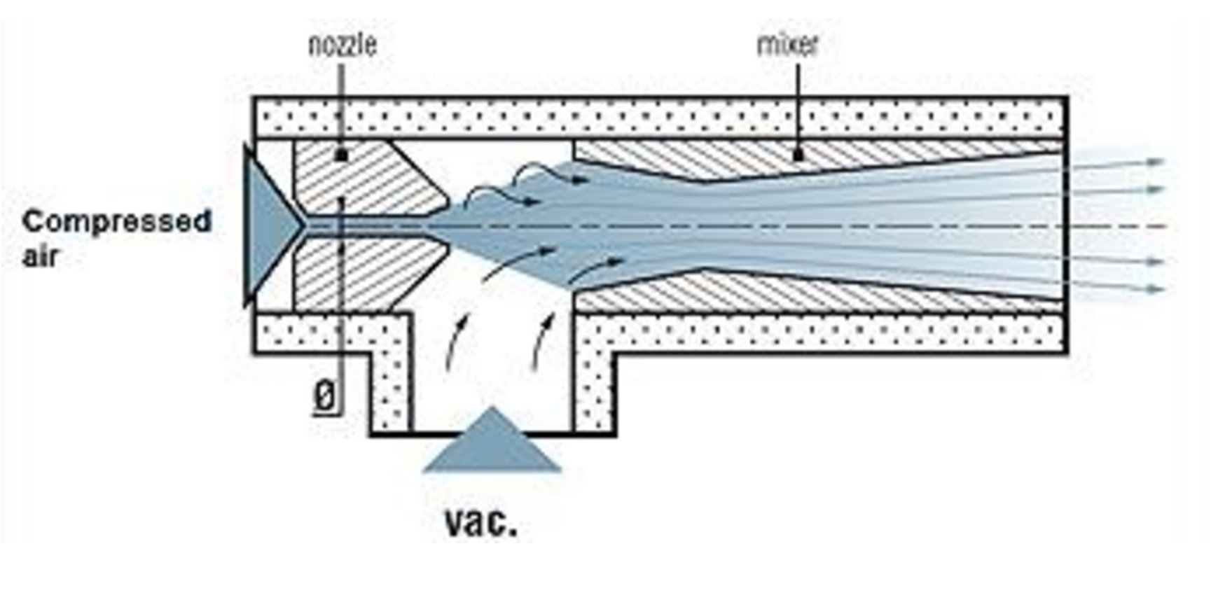
Figure 1: Venturi Vacuum Pump Principle
In this article, we will discuss three different systems which uses the principle of induction.
First system: HVAC Induction unit
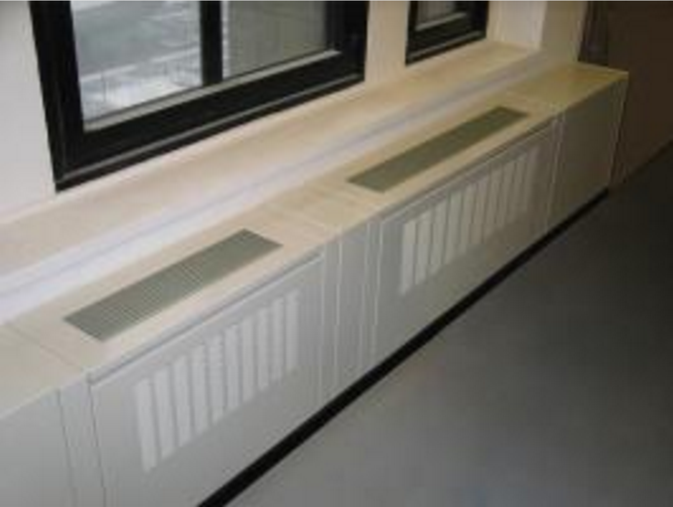 Figure 2: Perimeter Induction Terminal
The first induction system is the perimeter induction terminal. It was invented by Willis Carrier to overcome the issues of large central duct risers and extensive branching to many diffusers. His invention was smaller and consumes less energy than the existing HVAC system of this period. We found those induction terminal in office buildings, hospitals, hotels, etc. It was the system of choice for 1930’s to 1970’s.
Technically how does it work?
We first need an air handling unit (AHU) that provides fresh air. This give us a small AHU and few bulky ducts, since in most cases the primary air velocity is in the order of 15 to 25 m/s. This unit is composed of a fresh air damper, filter, a heating and cooling coil and a constant fan. The flow is set according to the number of people in the rooms. The AHU creates the primary air always at the same temperature for the inductions terminal. This primary air is passed through an array of nozzles in the terminal unit that creates a vacuum effect. This effect is the induction phenomena. The vacuum recirculates the air from the room through the terminal unit coil. The room air is called the secondary air. Finally, this air mixes with the primary air and is discharged in the room (see figure 3).
The temperature in the room is controlled by throttling the water through the coil with a valve or a damper which bypass the air around the coil.
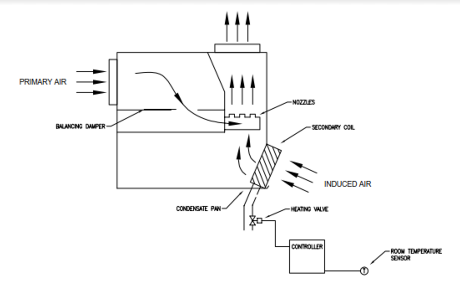
Figure 3: Perimeter induction terminal diagram
There are many variation of induction terminals to control the temperature in room space. Here are some examples:
- Reheat coil only (2 pipes induction unit system)
- The AHU produces the primary air always at the same temperature with heating and cooling coils. A heating unit produces hot water or hot glycol for the reheat coil in the induction terminal. The valve of the reheat coil modulate only if the room thermostat is in need.
- Single water coil (2 pipes induction unit system)
- The AHU produces the primary air always at the same temperature with heating and cooling coils. A heating unit and cooling unit produce hot and chilled water for the water coil in the induction terminal. There is a change-over valve which open or close due to the building mode of operation. The valve on the water coil can serve as either chill water coil or hot water coil depending on the mode of the system. This induction unit cannot cool and heat at the same time.
- Heating and cooling coils (4 pipes induction unit system)
- The AHU produces the primary air always at the same temperature with heating and cooling coils. A heating unit and cooling unit produce hot and chilled water for the heating and cooling coils in the induction terminal. The 4 pipes system consists of two separate cooling and heating water coils. Each coil has its own dedicated set of pipes and valve. Contrarily to the 2 pipes system, the 4 pipes system does not require a changeover valve. This induction unit can cool and heat at the same time and is not dependant of the actual mode of the building.
Nowadays, we find less perimeter induction terminal in new constructions. There were certain negative aspects of those system that became more significant. Indeed, excessive fan energy associated with the high pressure primary air requirements of the nozzles (up to 2 in. wc.) and rezoning difficulties did not meet the needs of new building occupancy profiles. There were also causes of moisture to condense coils during cooling operation and excessive noise due to the high pressure passing through the nozzles.
Second system: Induction VAV
Figure 4: Barcol-Air Induction VAV Terminal Unit
The second system is the Induction variable air volume terminal unit. It was created to solve the issue of cold air dumping with the traditional VAV unit. Indeed, the traditional VAV unit vary the airflow to maintain a constant temperature in the room. In a 100% heat load, the room is properly flush and everyone is happy. But if the heat load is reduced to 50% the room is no longer properly flush and the room becomes stagnant. Below 50%, due to the low air velocity, the air no longer travels along the ceiling. It will drop vertically from the diffuser to the space. This is called cold air dumping. The induction VAV unit will eliminate this problem with the fact that the room is always properly flush.
Technically how does it work?
The induction VAV terminal are designed particularly for systems with high variations in heat load. It is able to maintain comfort even in extreme load variations. This specific characteristic means that cold air dumping will never occur and that low primary air temperatures can be used.
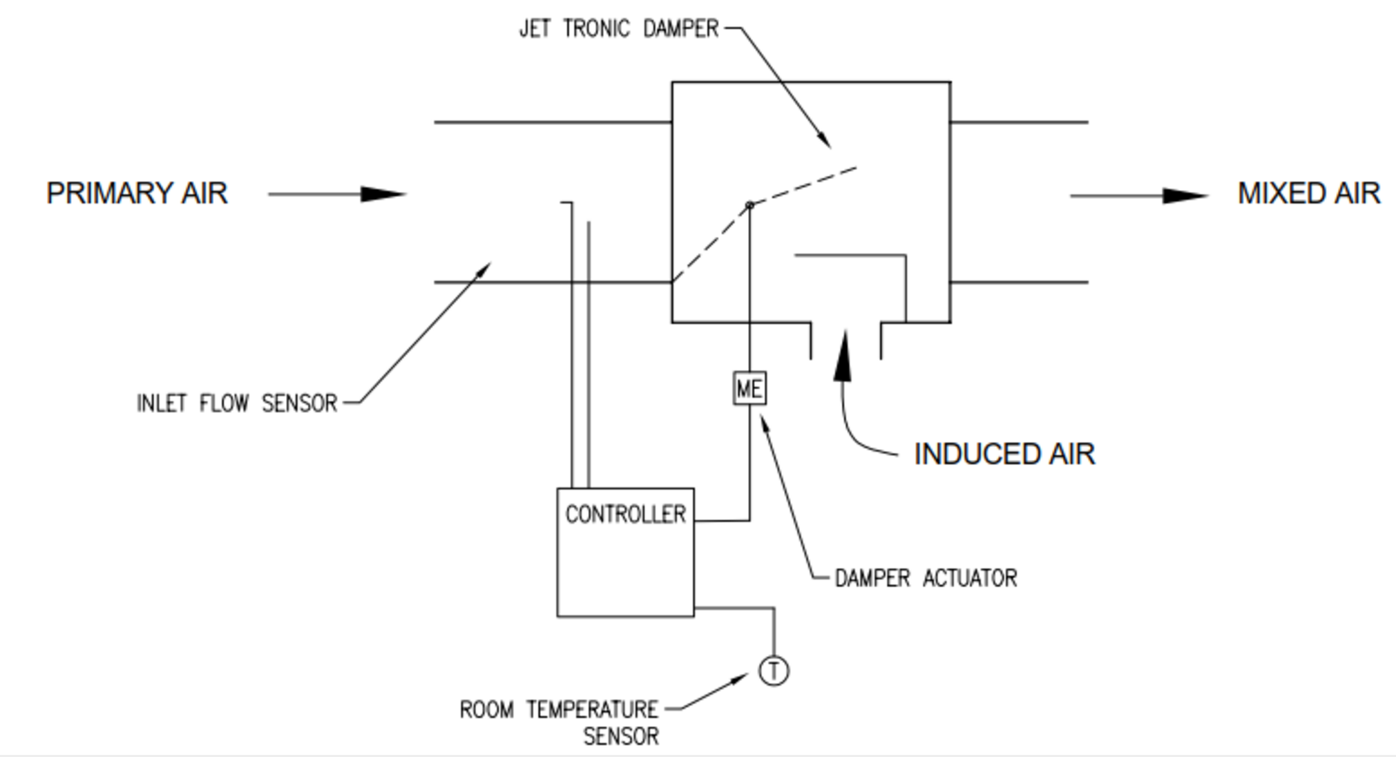
Figure 5: Induction VAV Terminal Unit
The main feature of this induction VAV unit is the jet tronic damper. This damper controls the amount of primary air volume at the same time, this creates a Venturi Effect which induces room air in the terminal. To maintain the temperature constant, the room thermostat modulates the jet tronic damper. The result is that in a 100% heat load the warm induction air is relatively low. While in a 20% heat load the warm induction air is higher. The mixed air volume always stays the same to maintain proper air distribution in the room, improving comfort and conserving energy.
This unit is an excellent alternative to fan powered air terminals. This one is quieter due to the absence of a fan and less maintenance.
They are many advantages for using an induction VAV unit:
- Energy savings
- Control range of 20 to 100%
- No cold air dumping
- Low noise production
For better comfort, it’s possible to install an water heating or electrical coil.
Third system: Chilled Beam
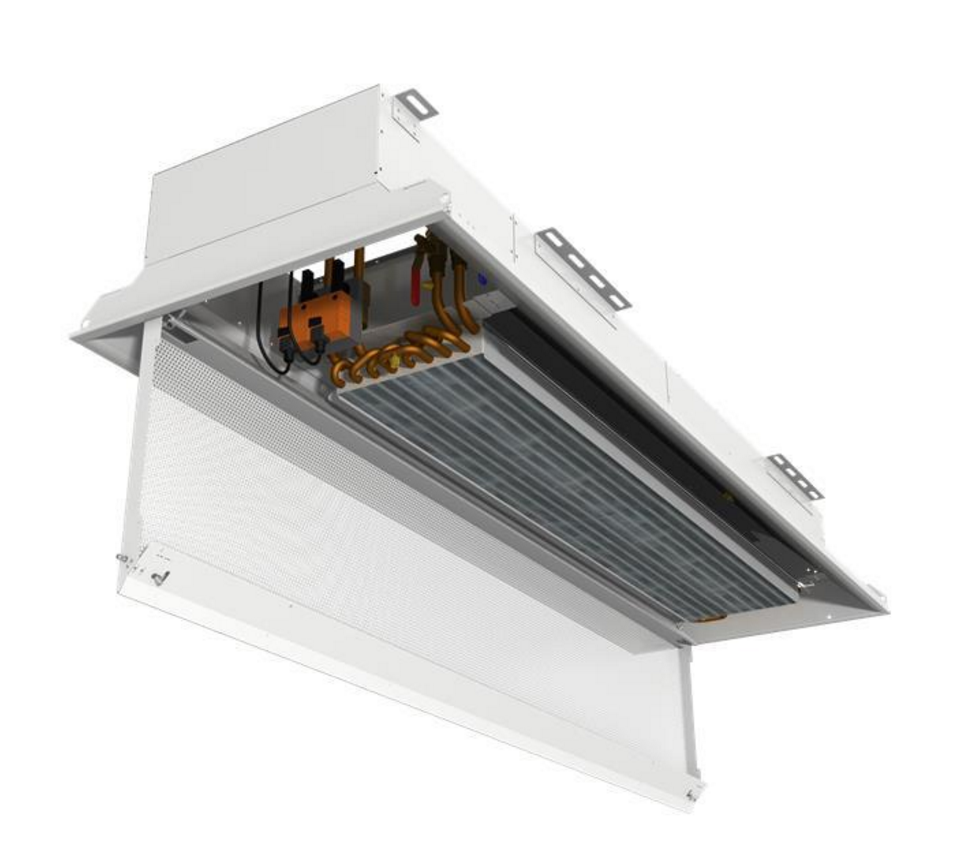
Figure 6: Active Chilled Beam Unit
Finally, the third one is the active chilled beam. They are two kinds of chilled beams. The first one is the passive chilled beam (PCB), a convective air motion is use to cool the space. The second one is the active chilled beams (ACB) which uses induction air to cool the space. This induction process allows an ACB to provide much more cooling capacity than a PCB. Therefore, they are more commonly used.
Active chilled beam
An ACB is consist of fin-and-tube heat exchanger contained in a housing that is suspended from the ceiling. The primary air passes through the nozzles, which induce air from the space up through the cooling coil. One of the biggest challenge of the ACB is to maintain a primary air with no humidity. Indeed, the chilled beam typically does not contain a condensate drainage system. Therefore, the primary air system must maintain the dew point of the indoor air below the surface temperature of the chilled beam to avoid moisture from condensing on the coil.
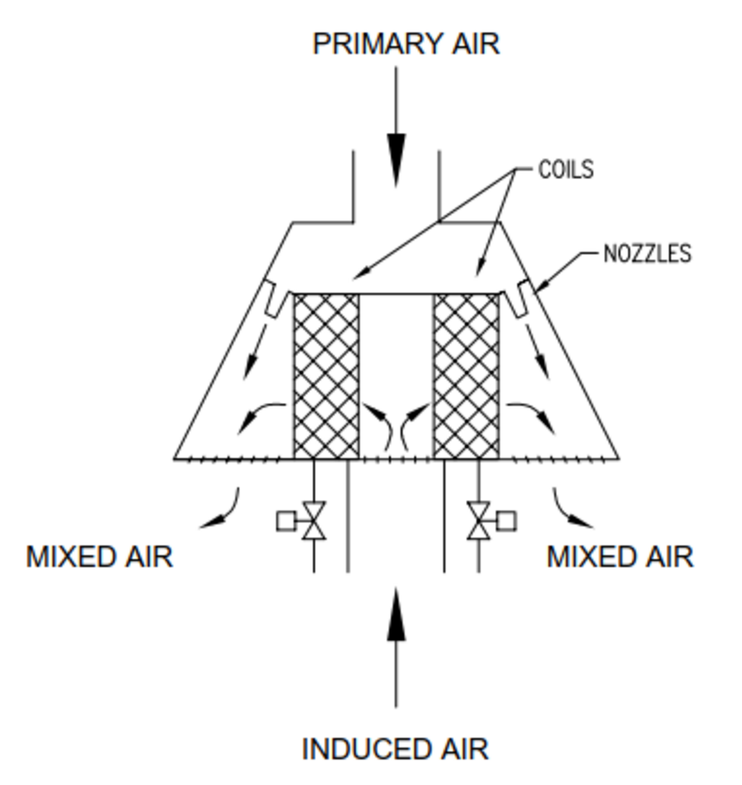
Figure 7: Active Chilled Beam Diagram
Air handling unit
The air handling unit (AHU) must deliver the require amount of outdoor air to each space for ventilation. The AHU must also dehumidify the outside air such that it is dry enough to offset the space latent load and maintain the indoor dew point low. Finally, the unit must deliver enough air to induce sufficient room airflow to offset the space sensible cooling load. More primary air there is, more room air will be induced through the chilled beam coils. This is cause by an high static pressure. However, a higher inlet pressure requires more fan power. To avoid the excessive fan energy like the high pressure perimeter induction unit from the 1930s to the 1970s, ACB are selected with an inlet static pressure between 0.3 and 0.5 in. wc.
Cooling and heating coils
There are the 2 pipes or the 4 pipes system design available. With the 4 pipes design, some zones can receive cold water for space cooling, while other zones simultaneously receive hot water for space heating. With the 2 pipes design, all zones receive either cold water or hot water. This kind of design would need to either add heat to the room with a separate heating system such as baseboard radiators or convectors.
In both design, there is a room thermostat which modulate the cooling or heating valve to maintain the room temperature constant.
For the cooling coil, the temperature must be relatively warm (between 58°F and 60°F) to prevent condensation. With a warmer water temperature, more coil surface area Is needed to provide the required cooling capacity.
Pros and cons
The pros of the active chilled beam would be:
- Smaller ductwork and smaller AHU than a VAV system
- Low sound levels
- Less energy consumption
- Improved indoor air quality
- No cold air dumping
- Lower maintenance costs
- Lower operation cost
The cons of the active chilled beam would be:
- Risk of water leaks
- Prevent condensation and moisture
- High installed cost
- Limited heating capability
For the moment, this is a new technology for the US. It is starting to emerge as an alternative to conventional VAV system. They have been used successfully in Europe for the past 20 years, where they have become standard practice.