
Imagine that you are in front of an open-air conditioner unit and see ice covering the pipes, what do you think the cause would be? And the solution? Could it be the amount of refrigerant in the system? It is more common for people to think that undercharging refrigerant in the air conditioner is the cause; however, many people have wondered if overcharging could have the same impact on the system. In this article, we'll explain the relation between pressures, temperatures, and enthalpies for an air conditioner, and how those thermodynamic properties can generate the coil icing. Additionally, there is an explanation of the main problems caused by undercharging or overcharging the system. Finally, all the possible causes for ice in the coil are covered.
Vapor-Compression Refrigeration Systems (VCRS)
A vapor-compression refrigeration system (VCRS) is the most common refrigeration system in the industry, and it is a good reference to explain the thermodynamic process. Figure 1 represents the components of the system, and includes two diagrams for each thermodynamic point. Let’s review the 4 thermal processes:
1-2 Compression: Increment of pressure in a compressor at constant entropy
2-3 Condensation: Heat rejection in a condenser at constant-pressure
3-4 Expansion: Throttling in an expansion valve
4-1 Evaporation: Heat absorption in an evaporator at constant-pressure
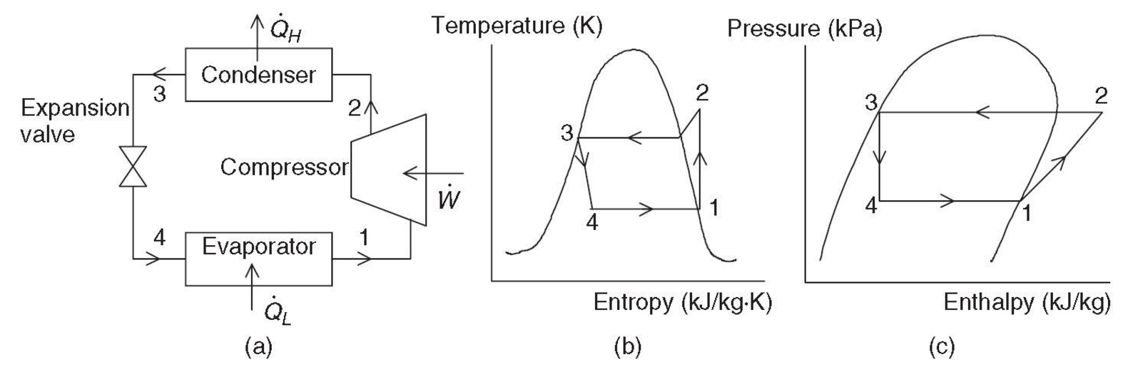
Figure 1: (a) A basic vapor-compression refrigeration system, (b) its T-s diagram, and (c) its log P-h. (Dincer & Kanoglu, 2010)
Why it is important to have the appropriate amount of refrigerant in the system?
If the system is overcharged, part of the refrigerant cannot be evaporated, and the compressor will work with the refrigerant in liquid phase. A compressor is a device that must be working with gas only; if it does not, the service life of this device decreases. On the other hand, an expansion valve is designed to handle liquid only, so this device has trouble with the refrigerant overcharging. So, as first impression we can say probably that having the appropriate amount of refrigerant or less is the solution; however, the evaporator is designed to take a specific amount of heat from the room, so the coil has a defined length and continues to expand the refrigerant through the coil. It means that if the system is undercharged with refrigerant, the suction and discharge pressures are below the levels required for efficient operation.
Consider the refrigerant R-410A: the pressure in the evaporator is 93.2 psia, according to the Table 8 (ASHRAE, 2013). The pressure value is used to find the saturation temperature. There are two important points we need to define, the bubble point and the dew point showed in the Mollier diagram Figure 2 and Figure 3.
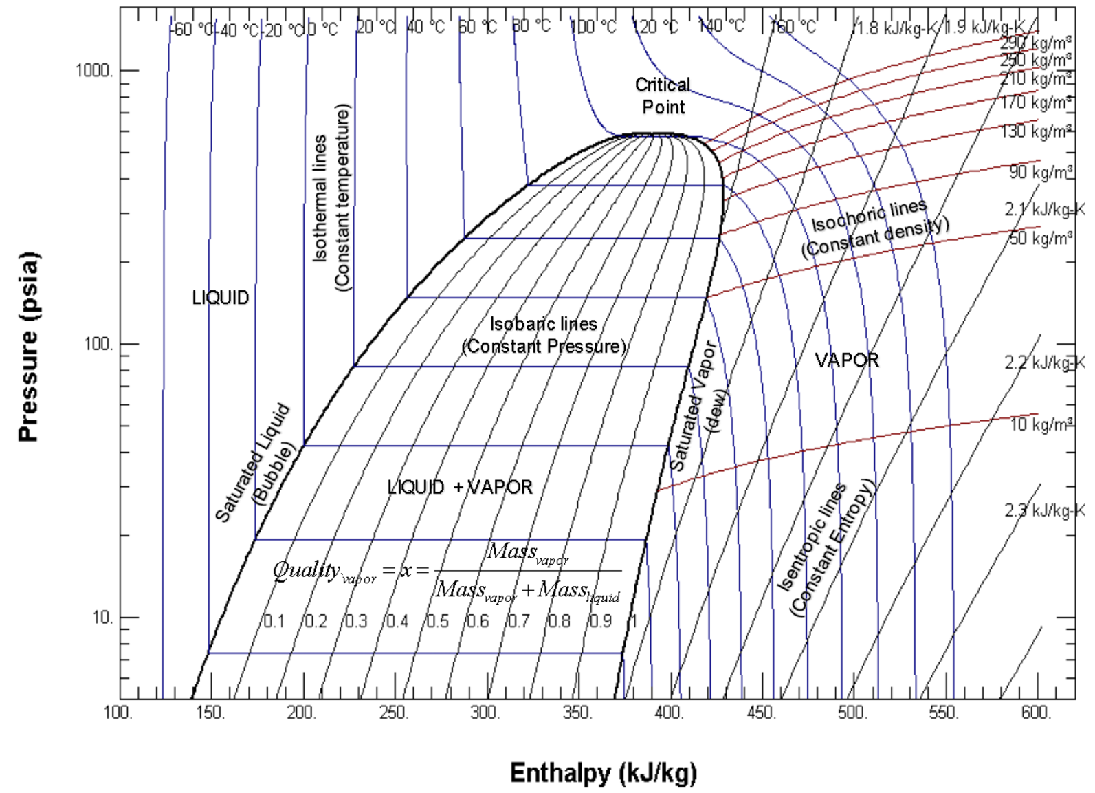
Figure 2: Mollier Diagram (Pressure-Enthalpy Chart) Single refrigerant. Courtesy: Honeywell
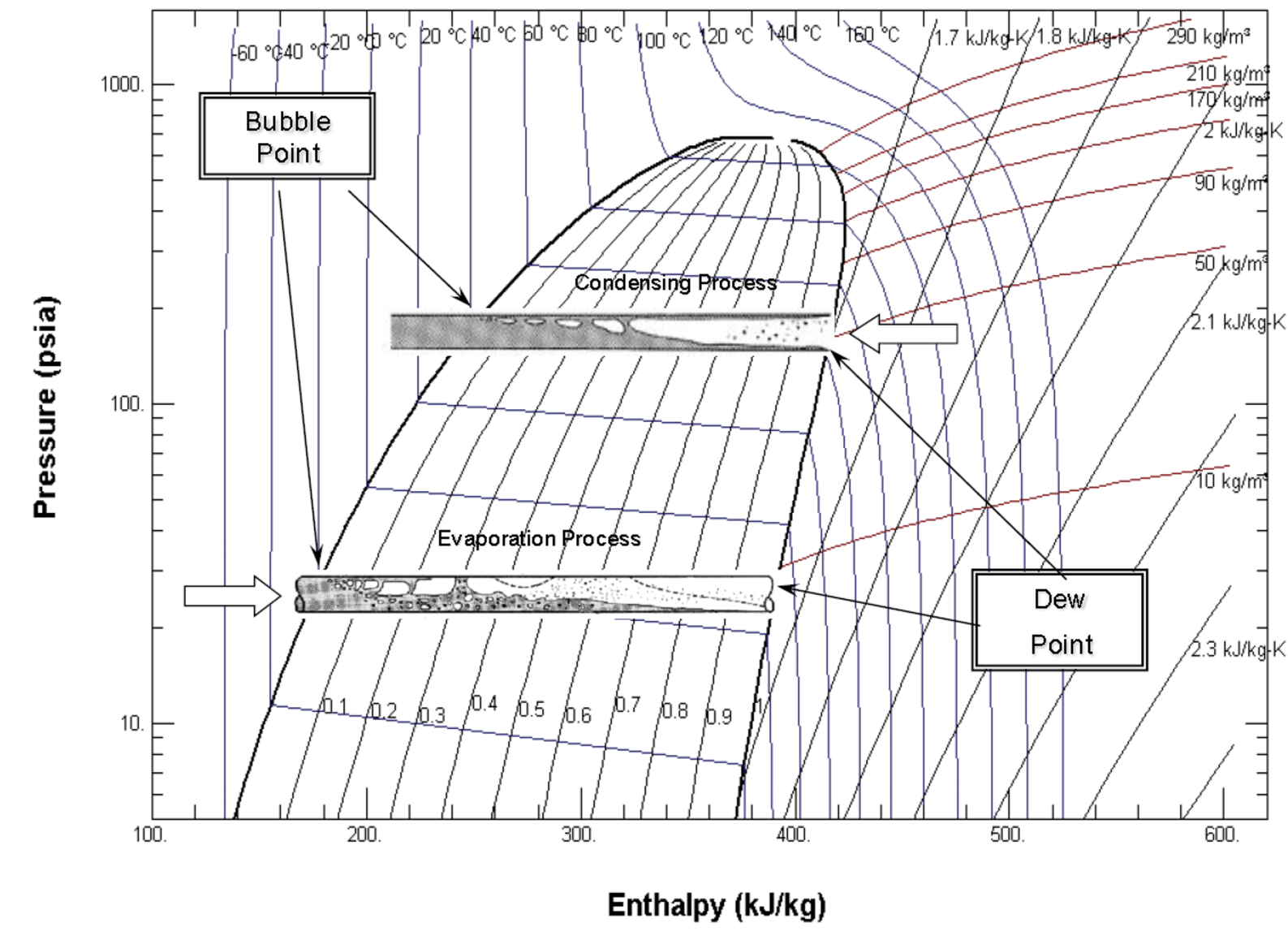
Figure 3: Mollier Diagram (P-h Chart) condensing and evaporation process. Courtesy: Honeywell
Bubble point: It is the point at which vapor begins to form or when the first bubble appears.
Dew point: It is the point at which liquid begins to form or when the first drop appears.
Was it interesting to learn about the thermodynamic processes involved in HVAC? It is a fascinating subject! The Mollier diagram is a graphic representation of a functional relationship between temperature, pressure, entropy, enthalpy, and quality of steam (the fraction of vapor with respect to water in the substance). The area to the left of curve is the saturated liquid region, and the area to the right is the vapor region. The point at which the two curves meet is called critical point; the importance of the critical point is that any additional pressure will change vapor into liquid.
So, the explanation above allows as to select the temperature needed, depending on the measurement location. Presently, almost all people have a smartphone, so let’s use this device to find the temperature. Android and IOS have the app “Refrigerant Slider” by Danfoss. You will find that it is easy to use. First, you need to select the refrigerant (R-410A in our case). Since the problem of icing is due to the evaporation process, you need to select the dew point. Finally, enter the pressure 93.2 psia, and you will get the saturation temperature. Figure 4 illustrates the pressure and temperature for dew and bubble points. You can see that the difference is almost negligible.
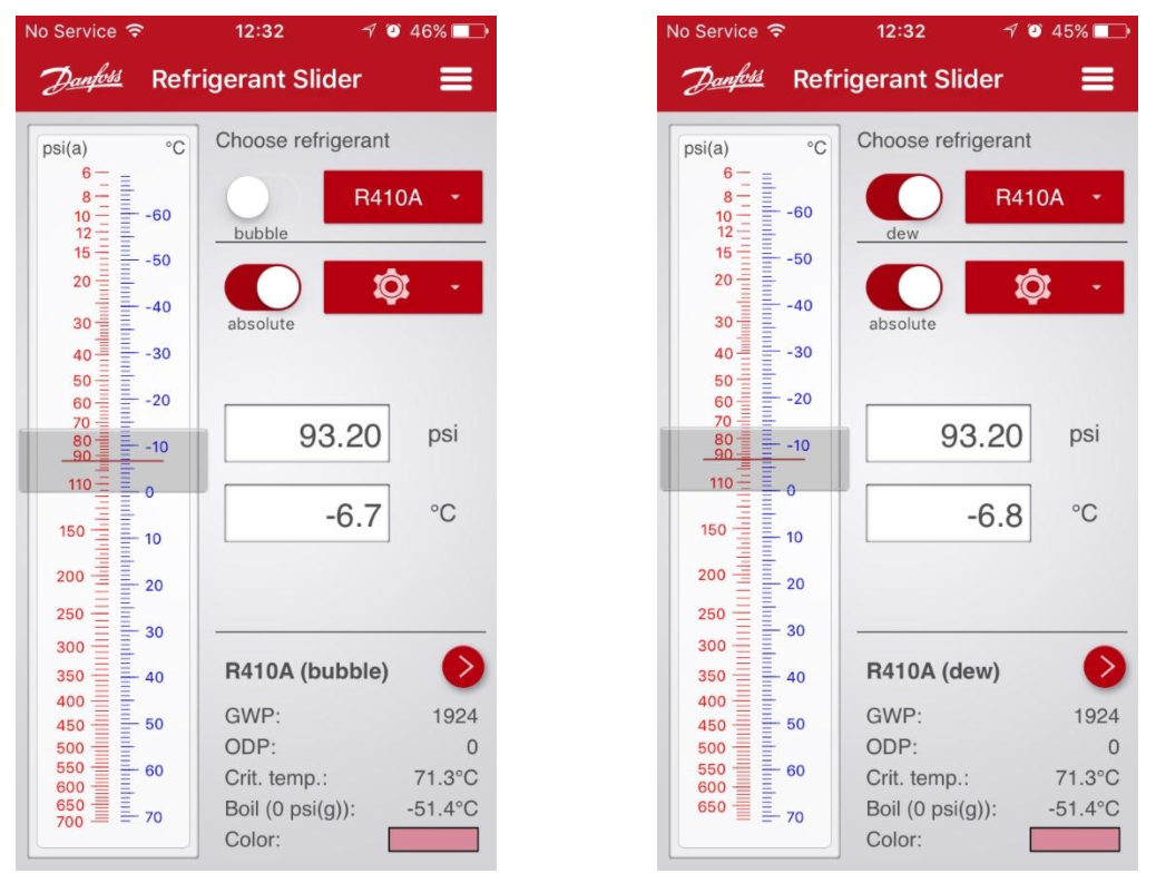
Figure 4: Refrigerant Slider App for bubble and dew points.
Until this point, we haven’t explained clearly how the ice is formed in the evaporator but we are almost there. If the system is undercharged, the pressure is less than 93.2 psi, so the saturation temperature is less than -6.8 °C. Pressure is directly proportional to temperature, so if the pressure decreases the temperature decreases. Having a lower temperature in the pipes means that the moisture contained in the air is going to freeze even if we have a normal airflow supplied by the blower. Even though the freezing point of the water is 0 °C—and in normal conditions the saturation temperature is less than that temperature (-6.8 °C)—ice won’t form because the air conditioner is designed to avoid icing by supplying an airflow by the blower. The heat transfer by convection supplies the heat needed to maintain the pipe without forming ice. Mathematic explanations exemplify this process, taking into account the sensible heat equation from the Airflow load calculation article:
Qs=1.1 (CFM)(∆T)
Where:
CFM: cubic foot per minute of air supplied by the blower
∆T=Tout – Tin. Tout is the temperature of air return from the room, and Tin is the temperature in the pipes.
If Tin is lower than the normal temperature and, ∆T is greater, the sensible heat required will be higher than the designed, and the surface of the heat exchanger will form ice taking the moisture from the air. We can state two more conclusions by checking that straightforward equation. Can you see that? First, if the air conditioner is not sized appropriately—meaning that the cooling load is much less than the air conditioner capacity—the air that comes from the room is going to be cold, and the ∆T will be small; therefore, the heat transfer rate will not be enough to avoid the coil to freeze up. Second, if there is a problem with the blower or the air filters are dirty, the CFM supplied will be less than that of normal conditions; as a result, the heat transfer rate decreases and the potential for ice to form increases.
Overcharged refrigerant
The compressor is the main component of the system since it is like the pump of the refrigerant. Replacing this component could be more expensive than replacing the whole unit. If there is an excess of refrigerant, it can flood the compressor and damage the mechanical components. Also, this problem will have an impact on your electric bills because the refrigerant pressure will increase on suction and discharge, and the compressor will demand more amperes to work. The extra amount of refrigerant in the system may cause the evaporator doesn’t complete the gasification process and that the compressor could work with liquid. In this event, the component will be destroyed in a short period of time for working with a different fluid instead of gas.
Undercharged refrigerant
Besides the freezing problem, this factor also has impact in regard to compressor damage because the refrigerant acts as a coolant inside the compressor. Having less than the correct amount of refrigerant increases the working temperature, and in time, the compressor motor will be overheated. The compressor has a thermal-magnetic overcurrent circuit breaker that can help to protect the component; however, if there is some damage before the protection is able to act, eventually the compressor will fail. Having more refrigerant or less refrigerant than the necessary will impact your finances. If there is not enough refrigerant in the system, the fluid won’t fill the evaporator; therefore, the cooling or heating capacity is decreased. Consequently, your air conditioner will be working harder than in normal conditions.
Additional causes of air conditioner coil freeze up
- Clogged capillary tube or a dirty, stuck thermostatic expansion valve: If there is a problem with the expansion device, the refrigerant won’t fill the evaporator and the temperature will decrease below normal conditions.
- Compressor contactor failure: There are some reasons for contact welding like unstable control voltage, currents that exceed the capacity of the contactor, etcetera. If the contactor is welded, the compressor won’t shut off. If the compressor is working constantly, the air conditioner is going to be cooling even at low temperatures causing the evaporator coil to freeze.
- The thermostat is malfunctioning: This device communicates the compressor and blower of the condenser at activation time. If it has damage, the compressor could be working without stopping causing the same effect previously stated.
- The condensing unit doesn’t turn off: The condenser will be pumping liquid refrigerant to the evaporator. If the blower of the evaporator is not on, the refrigerant won’t absorb heat from the room, and the condenser will freeze.
More information about the refrigerant charge
Through the whole article, we have seen the importance of having the correct amount of refrigerant in the system. Figure 5 presents the impact on the energy efficiency ratio (EER) by the percent deviation from correct refrigerant charge. The thermostatic valve can maintain efficiency better than the fixed-orifice. There are three common methods to check the refrigerant charge: pressure measurements at the suction and discharge, electrical parameters in the compressor, ventilator, etcetera, and the more accurate methods are the subcooling and superheat tests.
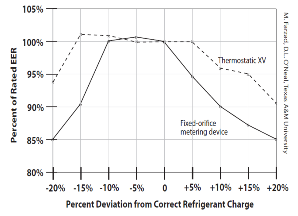
Figure 5: Comparison of thermostatic expansion valve TXV and Fixed-Orifice XV: EER versus charge at 95 °F outdoor temperature.
A superheat test must be carried out on air systems with fixed-orifice expansion ( XV, see link for commercial reference) devices while the subcooling test must be performed on units with thermostatic expansion valve (TXV, see link for commercial reference). The reason is that the TXV is a complex and precise device compared to XV. The subcooling test guarantees that only liquid is going to enter to the TXV. The superheat test assures that only gas is going to enter to the compressor.
Let’s going to use the help of the technology to understand how to measure the subcooling and superheat. Figure 7 shows the subcooling and superheat calculations using the App Check & Charge by Emerson. Key information is taken from the WAPTAC website (WAPTAC, 2017).
Subcooling test:
- Select the refrigerant (R-22 or R-410A).
- Enter the required subcooling recommended by the manufacturer. If the value is not tabulated in the manual, the range is between 10 and 15 °F.
- Enter the liquid pressure in psig.
- Enter the liquid line temperature in °F.
- Calculate the actual subcooling and compare with the recommended. Add refrigerant if the measured subcooling is 3 °F or more below the recommendation, otherwise withdraw refrigerant.
Superheat test:
- Select the refrigerant (R-22 or R-410A).
- Enter the indoor wet-bulb temperature (°F), condenser dry-bulb temperature (°F), vapor pressure (psig), and vapor line temperature (°F). Figure 6 shows the locations where the measurements must be taken.
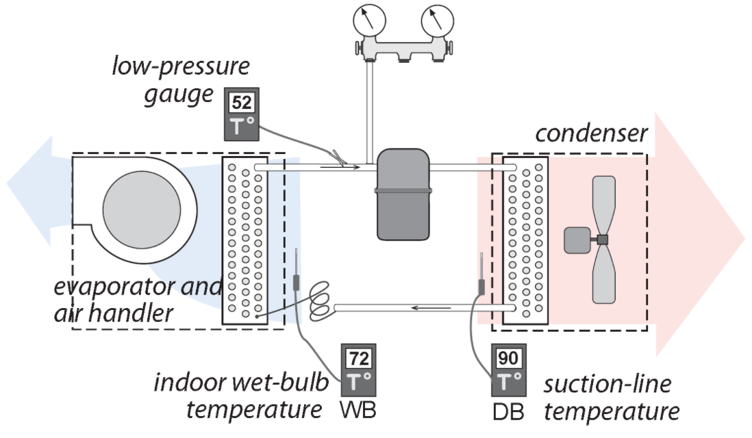
Figure 6: Locations where the temperatures and pressures must be taken.
- Calculate the actual superheat and compare with the recommended. Add refrigerant if the measured superheat is 5 °F or more above the recommendation, otherwise withdraw refrigerant.
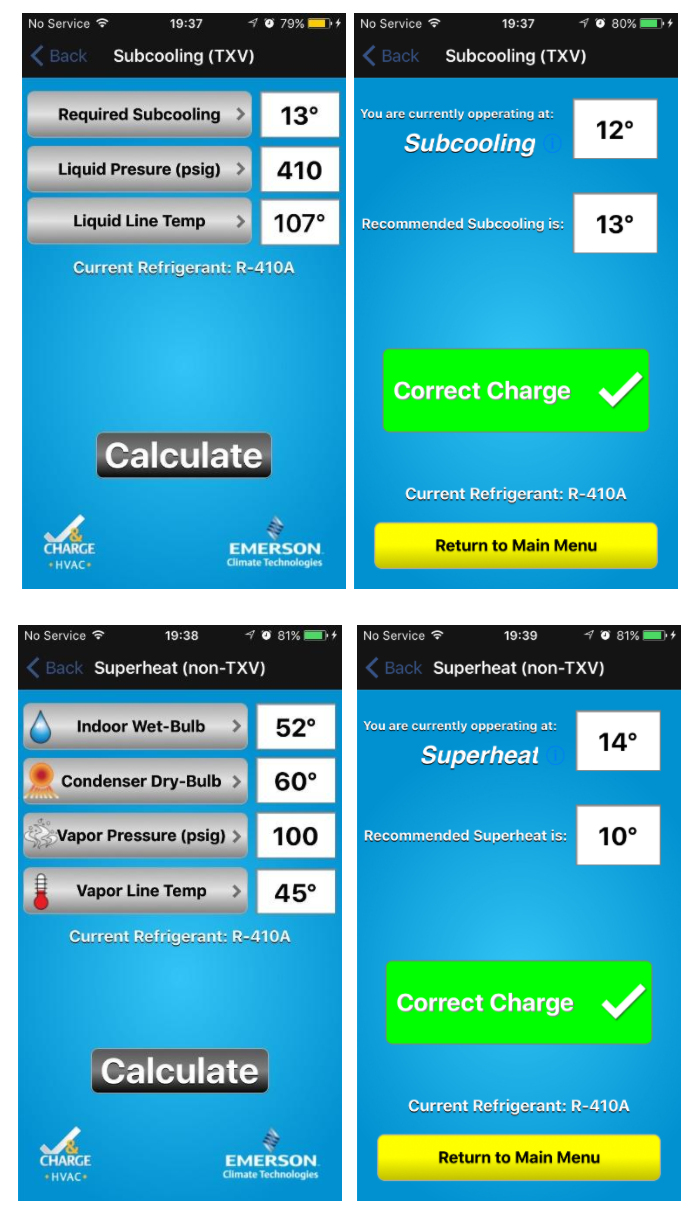
Figure 7: Subcooling and superheat calculations for R-410A from the App Check & Charge.
You could have doubt regarding the recommended superheat because it is not extracted from a manual. The App has the ideal superheat table loaded in its database. It is the same for all refrigerants and it is illustrated in Table 1.
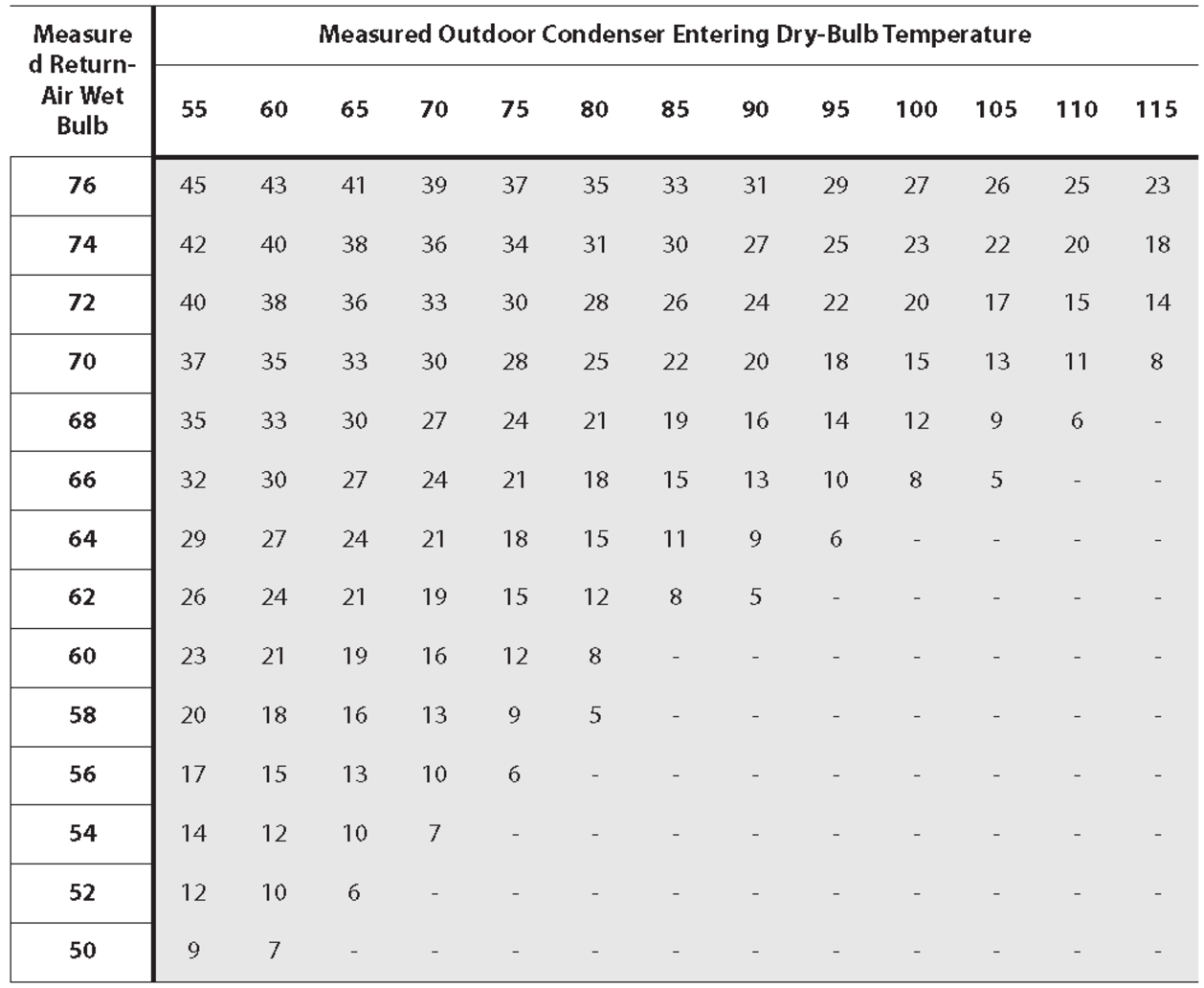
Table 1: Ideal Superheat Values for Different Indoor and Outdoor Conditions