
If you worked in HVAC controls and have worked with VAV boxes maybe you have heard the following terms before:
- Flow multiplier
- Pickup Gain
- Flow amplification
- K constant
Those are all synonyms for one thing: The K factor.
The K factor is a correction factor given by the VAV manufacturers to correct the installation issues of variable air unit terminals. But before we go too far… What is a VAV air terminal unit and how does it work?
Variable Air Volume Air Terminal Unit
The primary reason why we install an air terminal unit (ATU) in a room or space is to regulate the quantity and/or temperature of conditioned air delivered to satisfy the temperature requirements. There are many configurations of ATU available. (We compare VAV to VVT in a previous article.) The one we are looking at today is the variable air volume (VAV). This kind of ATU vary the airflow at a constant temperature, unlike the constant air volume (CAV) which supply a constant airflow at a variable temperature. Here are the advantages of using VAV ATUs instead of CAV ATUs:
- Better temperature control
- Reduced compressor wear
- Lower energy consumption with variable system fan
- Less fan noise
Pressure dependent
The pressure dependent VAV ATUs represent the basic control of a variable ATU. This type of unit modulates the damper actuator from the zone thermostat regardless of system conditions. This can be a problem when there are two or more zones on the same system since the controls of each unit affects the others.
For example, classroom A has 30 people and classroom B also has 30 people. Both are supplied by different VAV ATU but from the same central air supply. For both rooms right now, there is a specific cooling load. The room thermostat is satisfied. If in classroom A, 30 people were to leave the room, the cooling load would then decrease. The thermostat would now command the damper actuator to close the damper and reduce the flow. The result would be an increase in the system static pressure and an increase in the amount of air flow in classroom B. After a while, the thermostat in room B would sense a drop of temperature and reposition the damper actuator to reduce the air flow.
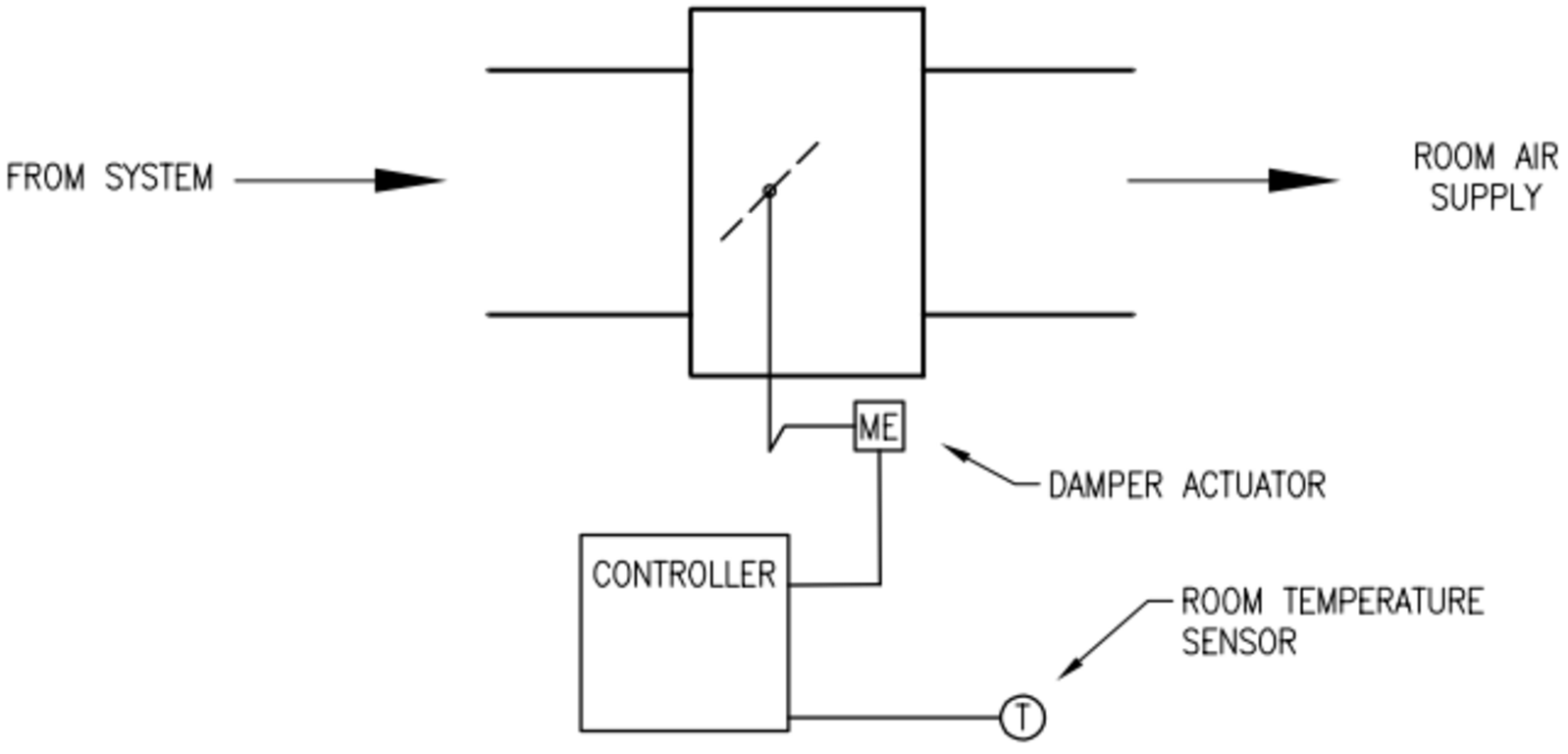
Figure 1: VAV pressure dependent ATU
Pressure independent
A pressure independent unit will deliver the required air volume to the room, even if the supply static pressure increases. In figure 2, a flow sensor is installed in the supply airflow to modulate the damper actuator to control air volume. It monitors and responds to the velocity of the air flow. The room sensor resets the airflow setpoint as the space thermal load changes. The airflow control loop can be set to maintain minimum airflow at unoccupied load conditions while maximum airflow can be set to limit flow to meet design conditions.
If we take the last example, the same 30 people in classroom A, leave the room. In this situation, the cooling load would decrease and the thermostat would command the damper actuator to close down the damper and reduce air flow. The result would again be an increase in the system static pressure. However, in this case, the ATU in classroom B would immediately sense the increased air flow through the inlet sensor and would command the damper actuator to reposition itself to maintain the required air flow.

Figure 2: VAV pressure independent ATU
Now what does the K factor has to do with all of this?
Well it has a lot to do with it.
Flow measuring
One limitation on the minimum airflow setpoint for the VAV box is the controllability of the box. Manufacturers list a minimum recommended airflow setpoint for each box size but the actual controllable minimum setpoint is usually much lower. The controllable minimum is a function of the design of the flow probe and the accuracy and precision off the digital conversion of the flow signal at the controller.
Technically, how does the flow measurement work? The equipment to measure directly the airflow velocity is way to expensive. Instead, the most often we find a probe in the air stream designed to sense total pressure on one side and static pressure on the other.
Total pressure=Static pressure+Velocity pressure
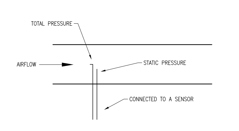
Figure 3: Pressure probe
The two pressures are connected to a sensor that will provide an air pressure signal that is proportional to the differential pressure of the airflow through the box. This differential pressure (DP) is the velocity pressure. This will help us calculate the velocity air flow. Here is the mathematical formula:
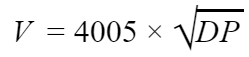
- V is in feet per minute (fpm)
- 4005 is a constant specific to this equation
- DP is in inches water column (w.c.)
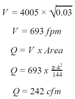
Now to calculate the air flow:

- Q is in CFM (cubic feet per minute)
- V is in feet per minute (fpm)
- Area (Duct cross sectional) is in square feet.
For example, if we have an 8 inch VAV box and we want to calculate the minimum CFM:

There is a rule of thumb saying that the minimum differential pressure the probes can measure is 0.03 ˮ w.c.
Those formulas are really just theoretical. Indeed, in normal conditions the air supply to the ATU is not at presumed conditions of temperature, humidity and at sea level. It also assumes a laminar flow at the measuring point. The recommendation is 5 to 6 time the duct diameter before the probes. But in reality we don’t have this amount of space.
This is the reason why VAV box manufacturers introduce the K factor. This constant is a representative of the duct area, geometry and dynamics of the pitot tube. It’s a number which can correct those real world issues and it’s done differently between manufacturers. The greater the K factor, the lower the controllable minimum. Now to calculate the flow we use this formula:
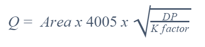
- 4005 is a constant specific to this equation
- DP is in inches water column (w.c.)
- Q is in CFM
- Area (Duct cross sectional) is in square feet.
For the same 8 inch VAV box we obtain this corrected flow:
I will use the K constant from a VAV box manufacturer.


How to use the K factor?
The K factor can help you choose the best range transducer for the pressure measurement. Indeed, if we have an 8 inch VAV box from the same manufacturer the maximum cfm is 1100 cfm. With the formula we can calculate the maximum velocity pressure we will have to measure.
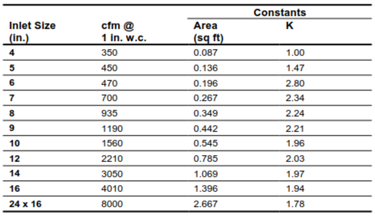
Figure 4 Appendix B: VAV Controller Flow Calculation Constants (Johnson Controls)
Rearranging the previous formula allows calculation of the differential pressure or the velocity pressure.
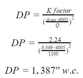
This will require an 0 to 1.5ˮ w.c. (0 to 375 Pa) range transducer.
But remember flow constants are based on laboratory data. Actual jobsite cfm readings may differ due to the accuracy of the balancer’s flow measurement equipment and due to turbulence and leakage.
The k factor is also use by the balancing crew. They will put the k factor in the controller and measure the air flow from the diffuser. They should get the same result at a differential pressure of 1 in w.c. from the chart. If not they would be changing up or down the correction factor until the flow reading matches the chart.
Related Products in This Article
Variable Frequency Drives (VFDs): Siemens